Description
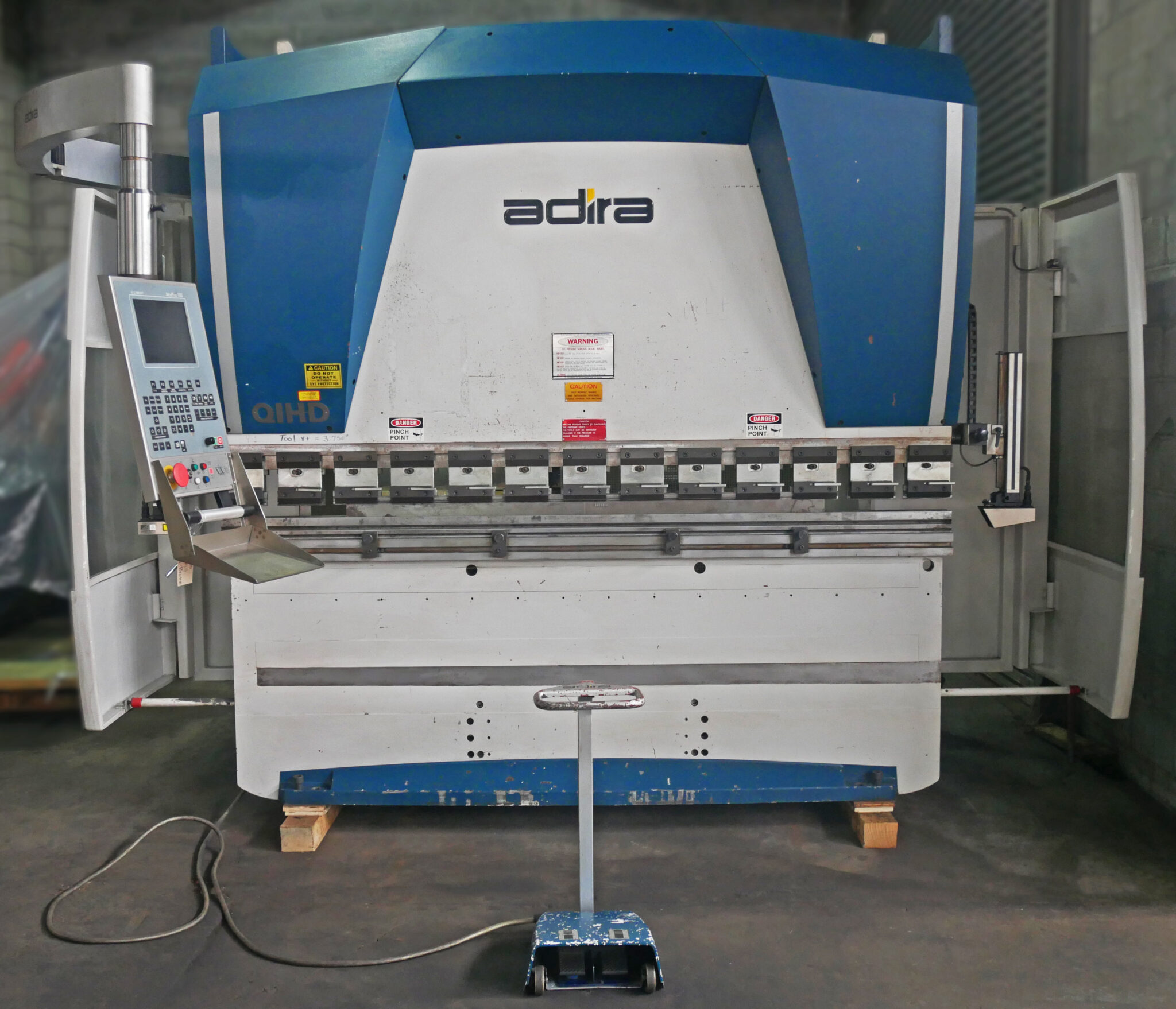
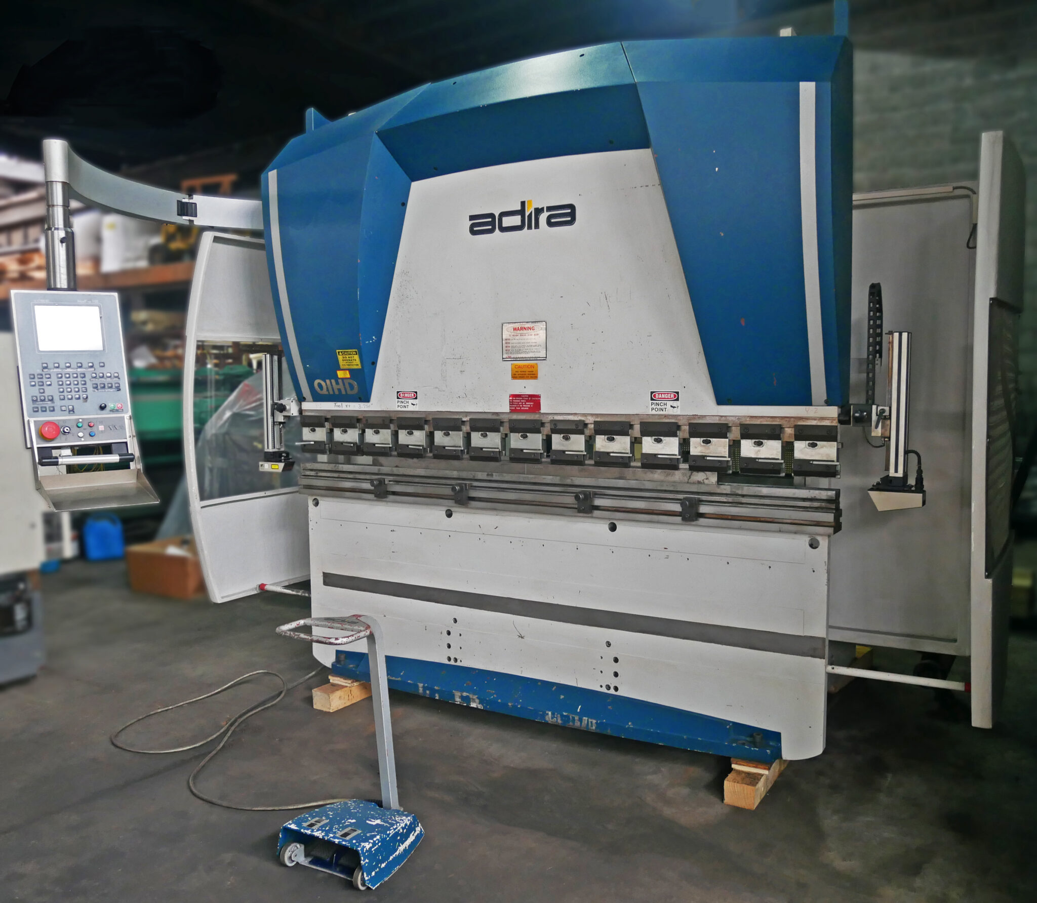
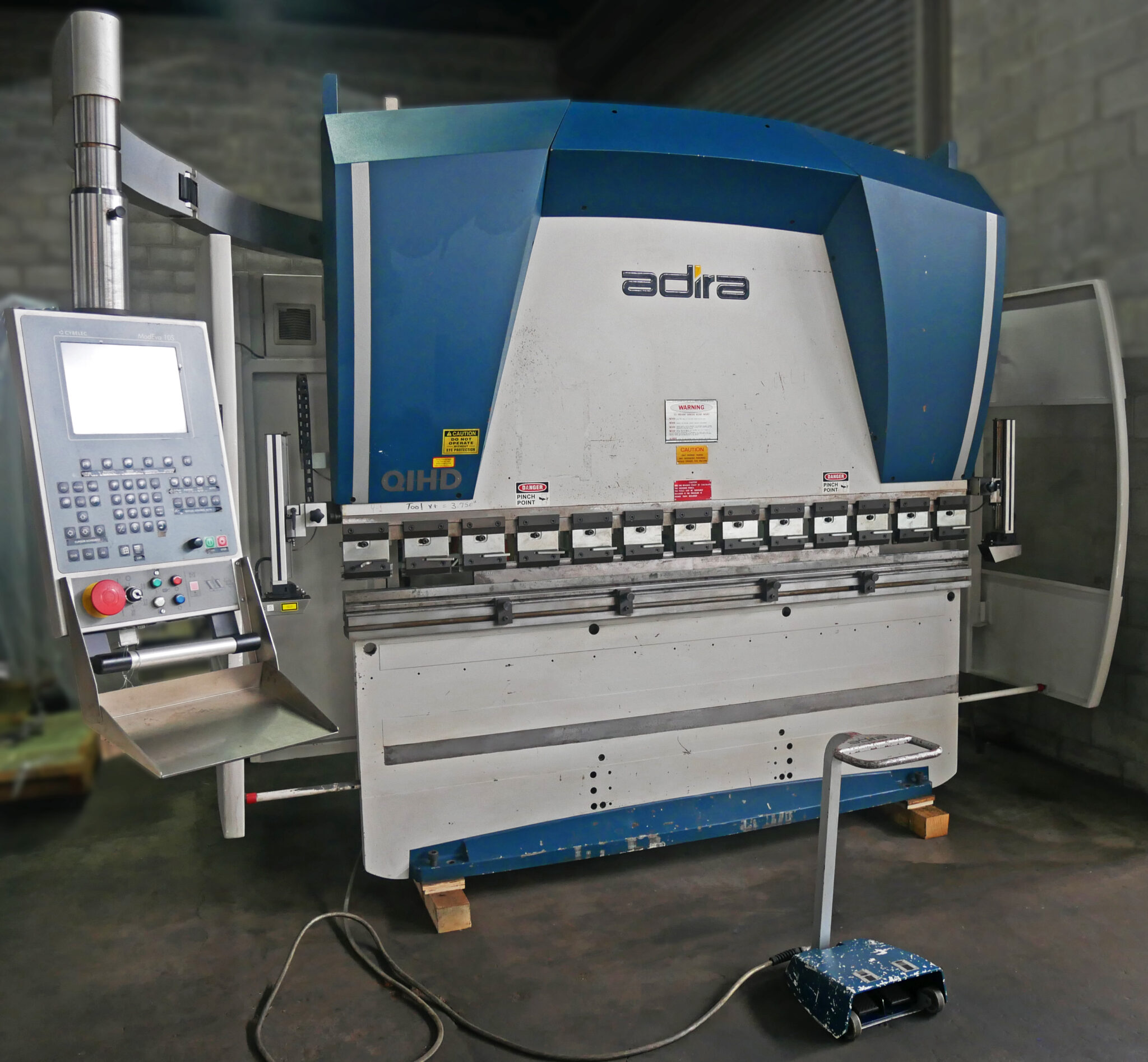
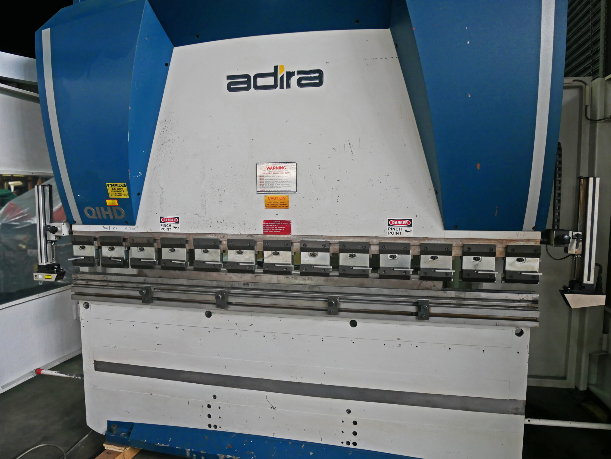
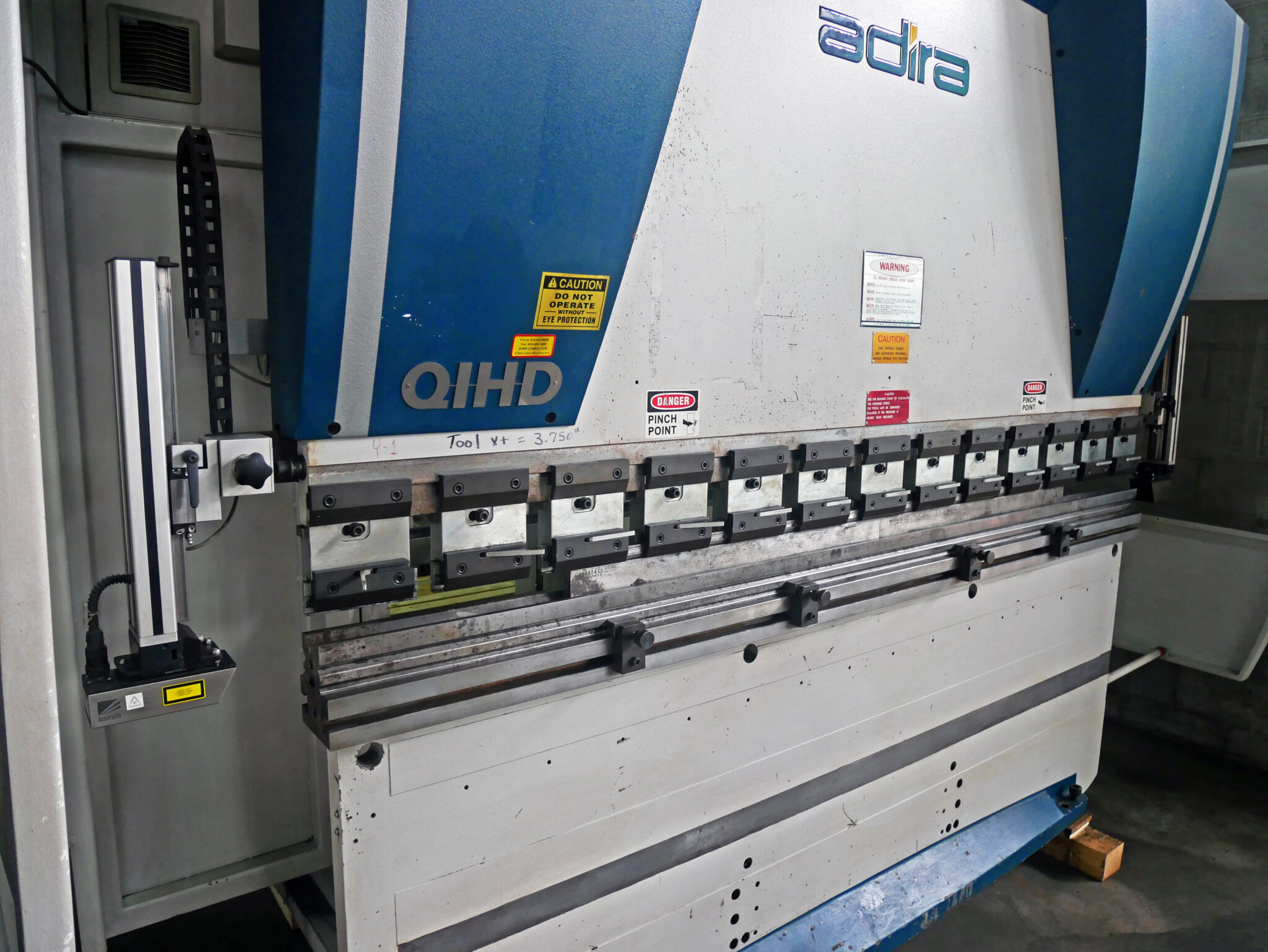
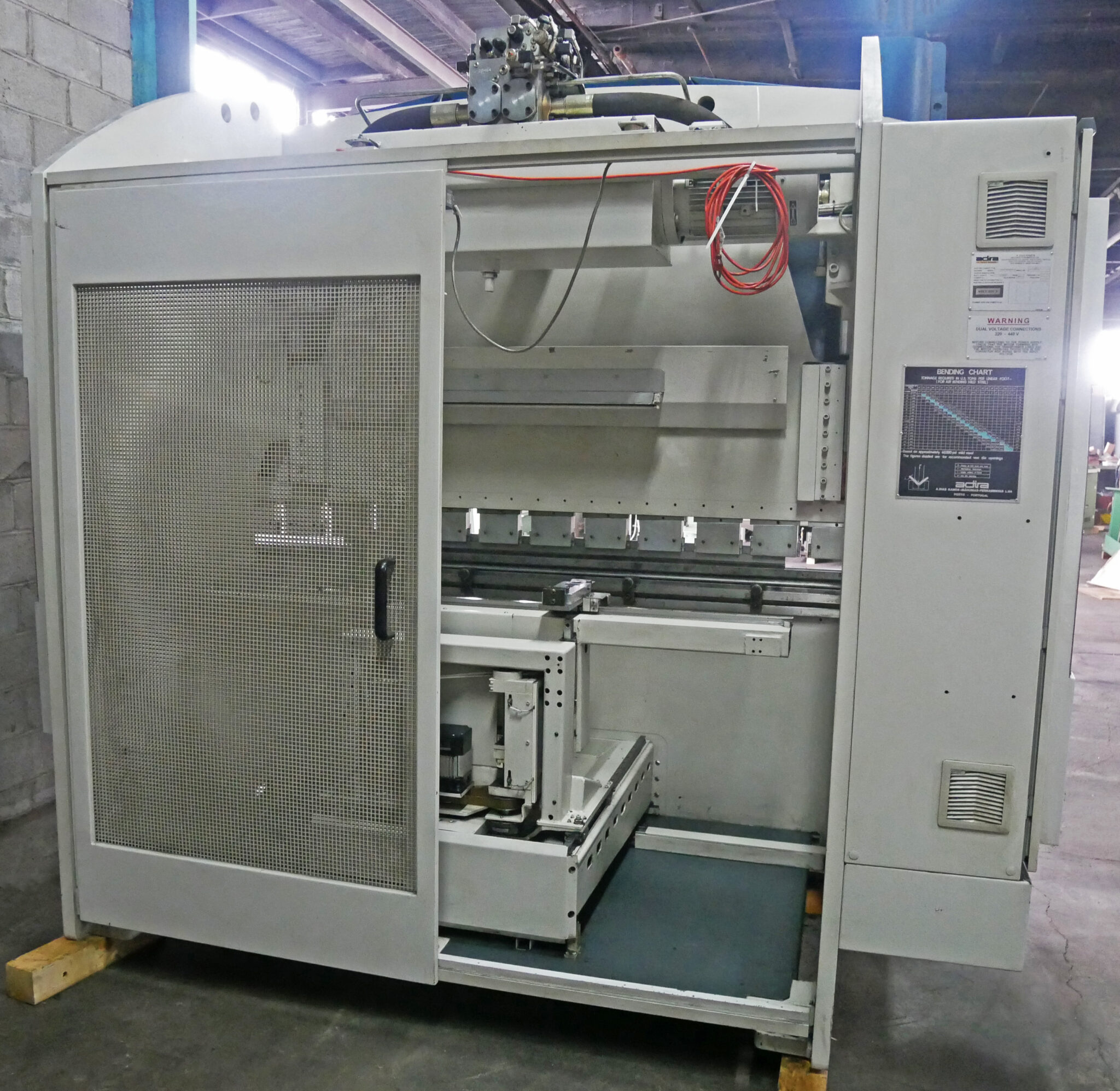
Adira 8′ x 90 Ton DNC-Controlled Hydraulic Press Brake with ModEva 10 Control, QIHD 8025 PLS
Inventory # 9579
Model: QIHD 8025 PLS with Factory Refurbished Control
S/N: 6514/11969
Hours:
On Time: 2,834 Hours, 21 Minutes as of 03/25/2025
Specifications:
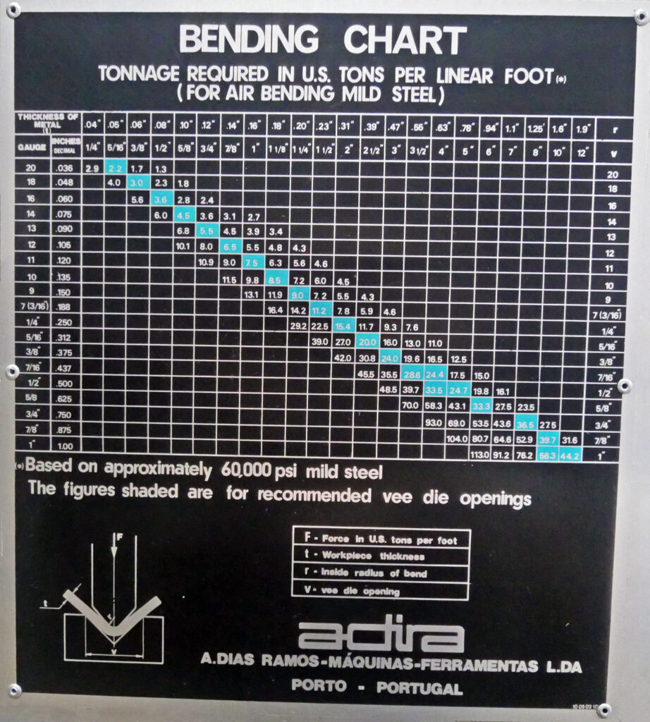
Capacity: 90 Tons
Max. Bending Length: 8′ (98″)
Distance Between Housings: 80″
Adjustable Stroke: 6.3″
Max. Open Height: 12.2″
Throat (Gap): 12″
Working Speeds (3):
Quick Approach: 3.15″ /Sec.
Bending: 0.41″ /Sec.
Return: 2.98″ /Sec.
Motor: 220v, 440v / 3ph (Pre-Wired 220v)
Standard Features/Equipment Included:
SEMPR System: Accurate ram depth positioning system with ram stopping point and machine repeatability equal to or greater than +/- 0.0004″ (.01 mm)
AF Wizard: Simple/quick adjustment of bending depth under load
CPS: Constant supervision of ram position enabling the programming of stroke, speed, change point, and management of structural deflection
CPS with AF Wizard provides a teach mode for parts set up manually
The frame is a robust, welded monoblock fabrication
Dual cylinder system
Built-in hydraulic and electric overload protection
Deep gaps in side frames
Quick approach and return speeds
The parallelism between the moving upper beam and fixed lower beam during descent and ascent is ensured by two servo-valves electrically controlled by DNC (Axes Y1 and Y2)
The measuring of the ram position is made by two linear encoders located on each end of the upper beam. As the reference is always measured in relation to the bed, the ram position on bending depth is independent from the work length
The bending depth (ram stopping point) is controlled by servo-valve from information given by the DNC, which provides the position where to stop
Slow approach in manual mode for total alignment
Upper moving beam guided at four points with adjustable gibbs made of self-lubricated material and with maintenance-free bearings
Easy adjustment of the bending depth under load over the plate being bent, with programming in 0.0004″ increments. The figure reached with the adjustment is easily entered into the computer (Teach-in)
Repeatability of the ram is not affected by the bending length, hydraulic pressure, oil temperature, or load location on the beam
Since the load location does not affect the bending accuracy on QIH SYNCHRO machines, the distance between housings can be used for different sets of tooling (the appropriate multiple tools set up on the bed at the same time)
Long and adjustable stroke of hydraulic cylinders for maximum machine and tool flexibility
Hydraulic drive including complete hydraulic system
Control panel including necessary selector switches and pressure gauge
One wide lower bed bolted to the lower beam to allow flexibility with tooling
One instruction manual, programming manual, and DNC operation and service manual
Motor and controls. Electrics for 3/60/220/440. Low voltage at the controls. Emergency stop palm button. Key-lock switch for ON/OFF for the power supply
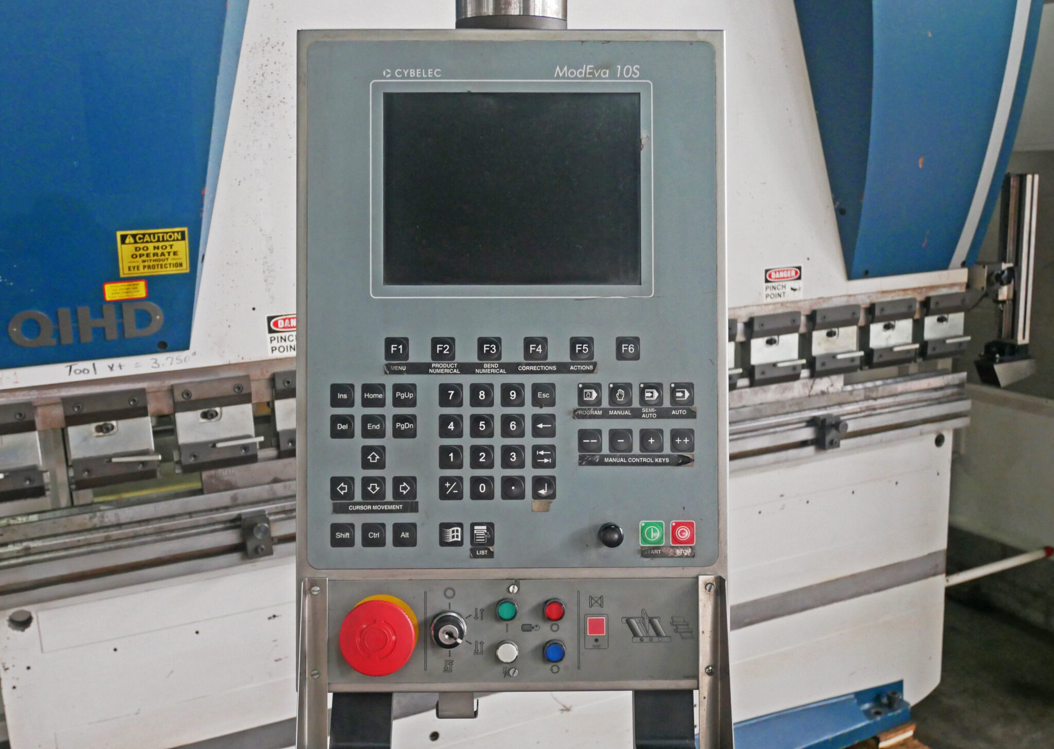
DNC Control System “CYBELEC” Type ModEva 10, 2-Dimensional Color Graphics Control:
Programming of the bending angle in tenths of a degree. The DNC automatically calculates the bending depth required according to the plate characteristics entered and the geometric characteristics of the tooling
Programming of the ram position including tilting for tapered bends (cones), X and R axes
The tooling library allows for the programming of the geometric characteristics of tooling
Calculation of the tonnage necessary for the required job with the chosen tooling. As a result, an extra tooling protection is provided against concentrated load
Easy and quick control and programming of bending tonnage
Tonnage programming on special coining (bottoming) or on bending (air bending) jobs
Absolute and relative programming for axis X (important on bump/radius forming)
Calculations made by the Cybelec ModEva 10:
– Approach/bending speed change point
– Position to change from a high-speed approach to a slow bending speed
– Pinch/point – important when it is necessary for a back gauge retraction to allow for more room in the production of reverse bends and to prevent the flange from hitting against the gauge fingers
Programming of Different Points According to Linear Size:
– Top limit of stroke
– Back gauge retraction of the pinch-point
– Programming of dwell time (beam under load)
The Machine Axes:
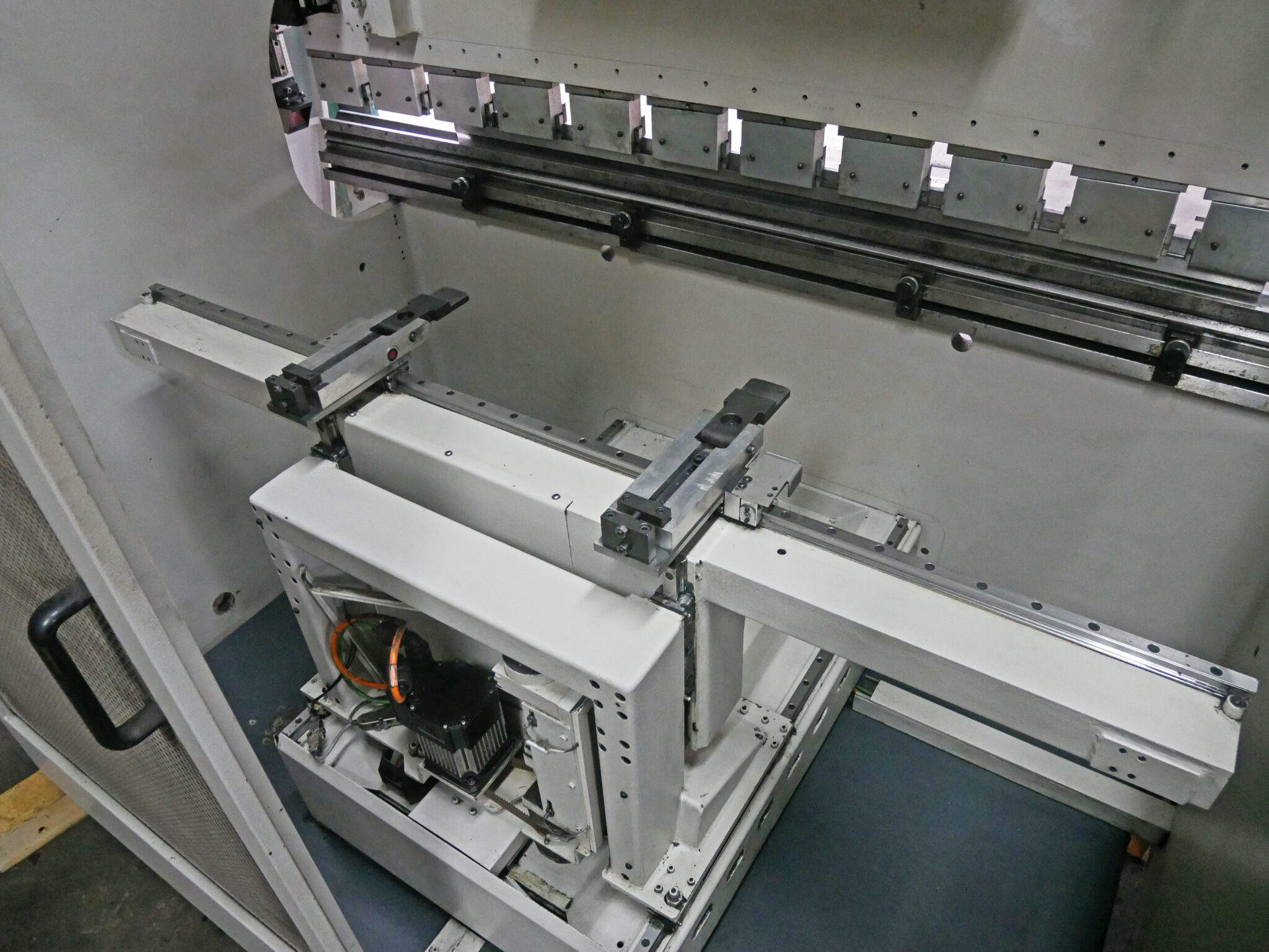
X-Axis: Programming of flange dimension/back gauge position
– Gaugeable Reach: 40″
– Back Gauge Travel: 24″
– High-Speed Back Gauge Travel: 1,195″ /Min.
Y1, Y2 Axes: Programming of the ram position including tilting for tapered bends (cones), X and R axes
R Axis: DNC-controlled, servo-controlled motorized vertical movement (height adjustment) of each back gauge finger together in relation to the die, range 7.87″
Positioning accuracy of +/- 0.0004″ for X-axis front-to-back movement
The carriages, fitted with recirculating bearings, run on hardened and ground ways
The carriages are positioned by a high-speed AC brushless servo-motor that drives hardened lead-ball screws
Tooling System:
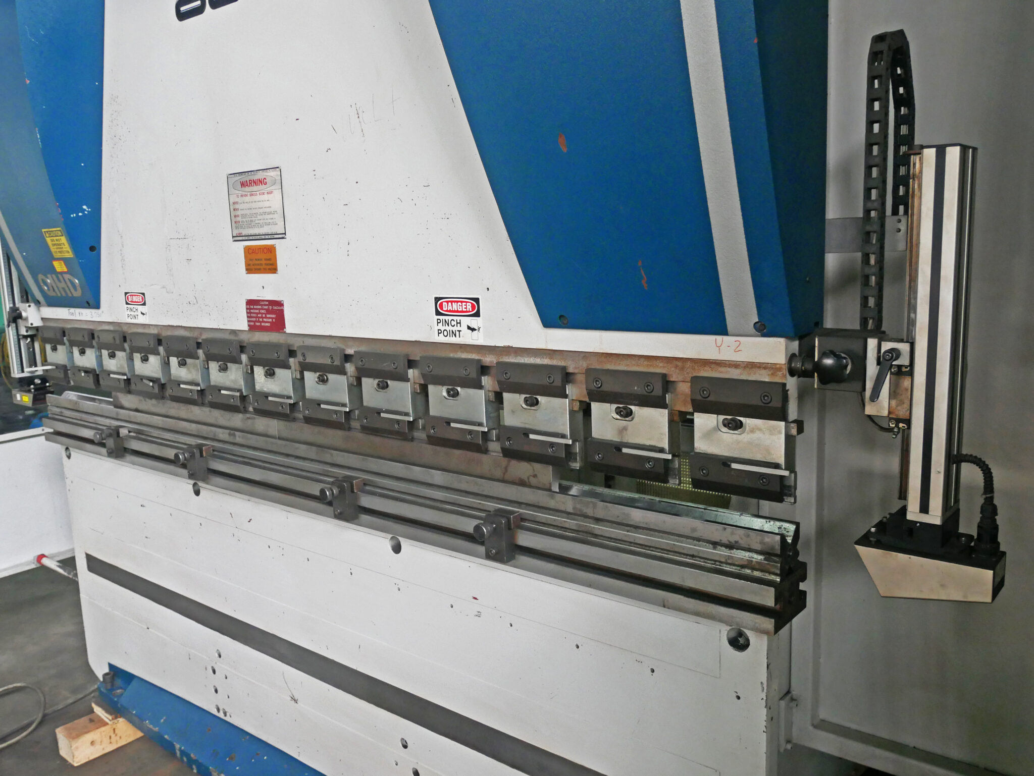
One set of manual quick-release adjustable punch holders will hold both American and European-style forming punches. These punch holders allow the operator to crown the upper punch to compensate for deflection or tooling wear, and provide greater flexibility when forming boxes and panels. Punch holders feature graduations for ease of setting
Mechanical Specifications:
Dimensions: 104″ x 59″ x 106″ H
Weight: approx. 10,200 lbs.
FOB Our Baltimore, MD Warehouse

